Programming an STM32 Timer for a Synthesizer DCO
How to easily program an STM32 timer to produce a frequency-accurate square wave to use for the core of a digitally controlled oscillator.

Yesterday I talked about the motivation for playing around with a design for a DCO module and noted how the STM32's timers seem particularly well suited for the task of creating a frequency-accurate square wave as the basis of the module. Today I'll show a little about how I achieved this.
I started programming my NUCLEO-L432KC board by using STM32CubeMX as I now always do. Conveniently the development boards are predefined in the tool so you can elect to have everything preconfigured for you. This helps out by letting you know which pins are already wired to something on the board and prevents you from accidentally trying to use a pin dedicated to some other function.
After setting up some of the stuff that I use for every project (FreeRTOS and a means to printf to the board's uart pins) I went to the clock tab to make sure I was getting the full 80MHz out of the chip so I'd have as much resolution as possible for the timers.
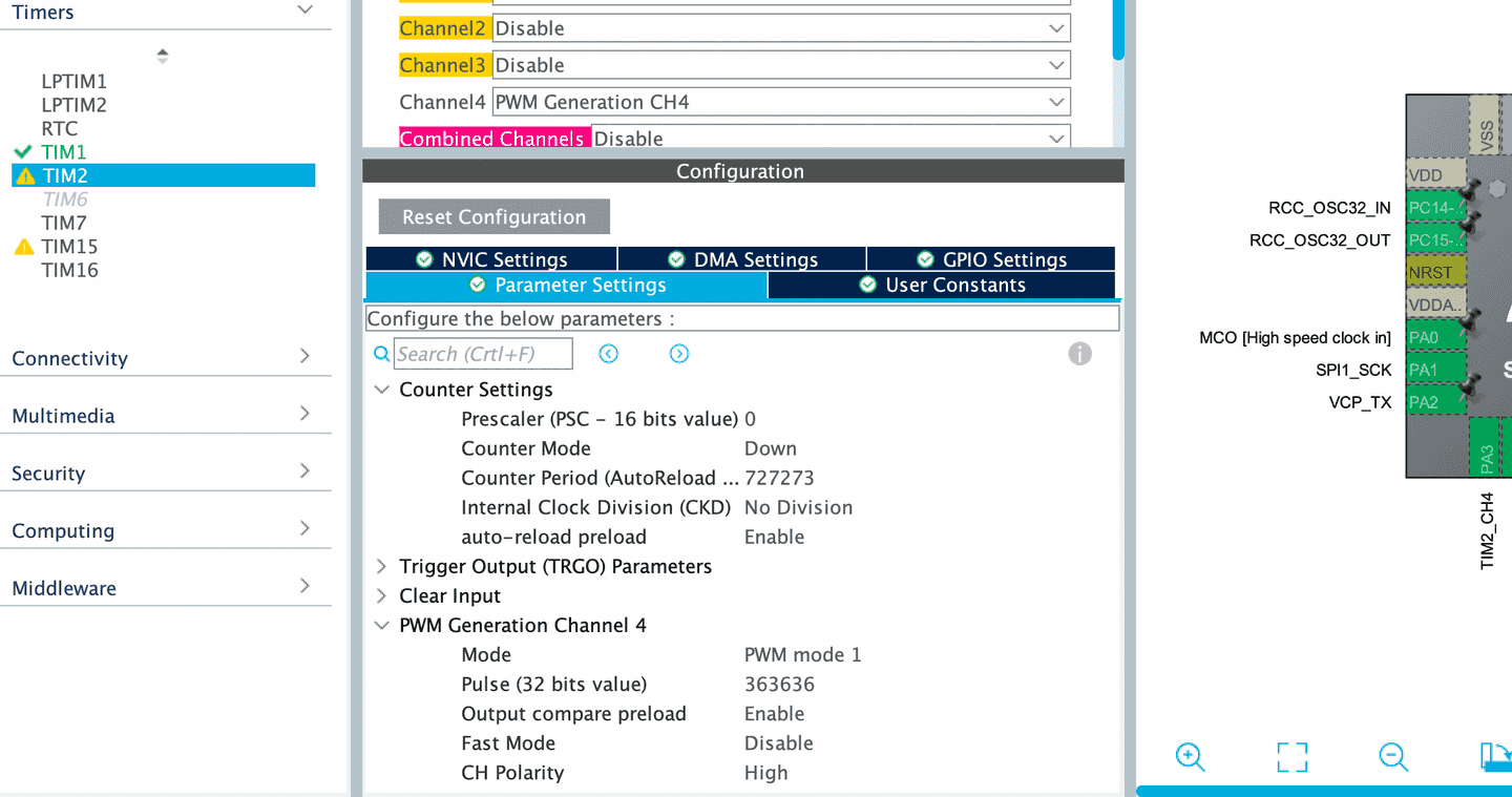
After that basic configuration I headed off to one of the available timers, in this case TIM2. There I set the mode to have PWM generation on channel 4. Under the parameters I set the counter mode to DOWN as this should always insure that if I set the counter value to something else it won't run off above the comparison value (although I think the way the timers reload that may never be an issue). Then the next important thing to set is the count the timer will start at each cycle, in the initial case I used 727273 which at an 80MHz clock should give a frequency of 110 Hz or the musical not A2. Finally I set the PWM generation pulse to 363636 which will give a 50% duty cycle to this square wave (which may not be absolutely necessary given how only one edge will be used downstream).
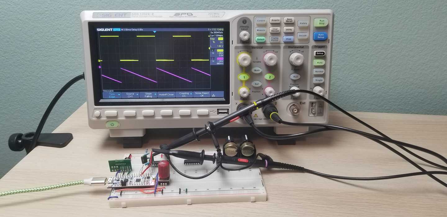
Finally, inside the main portion of the program itself I need to remember to turn the timer on with a HAL_TIM_PWM_Start(&htim2, TIM_CHANNEL_4);. At this point I could load and run my program and observe a nice 0 to 3.3V square wave on channel 4 of timer 2.


