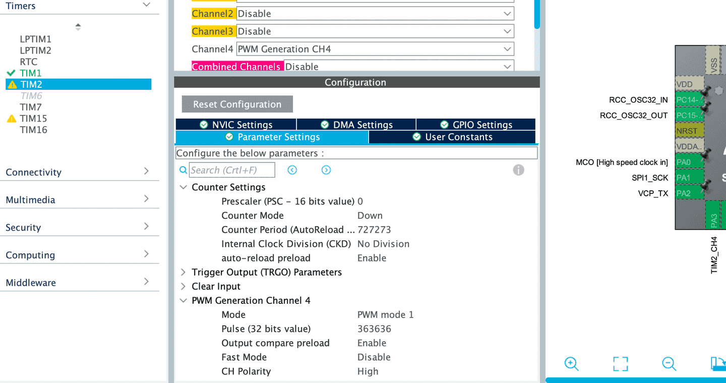
DCO Sawtooth: Clocked Ramp Reset
Using a clock to reset the sawtooth's ramp
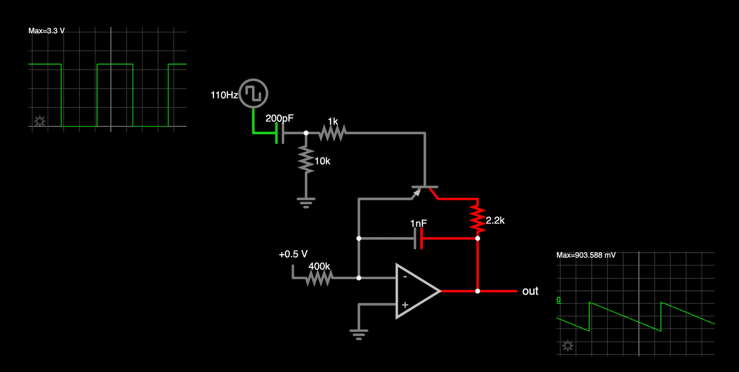
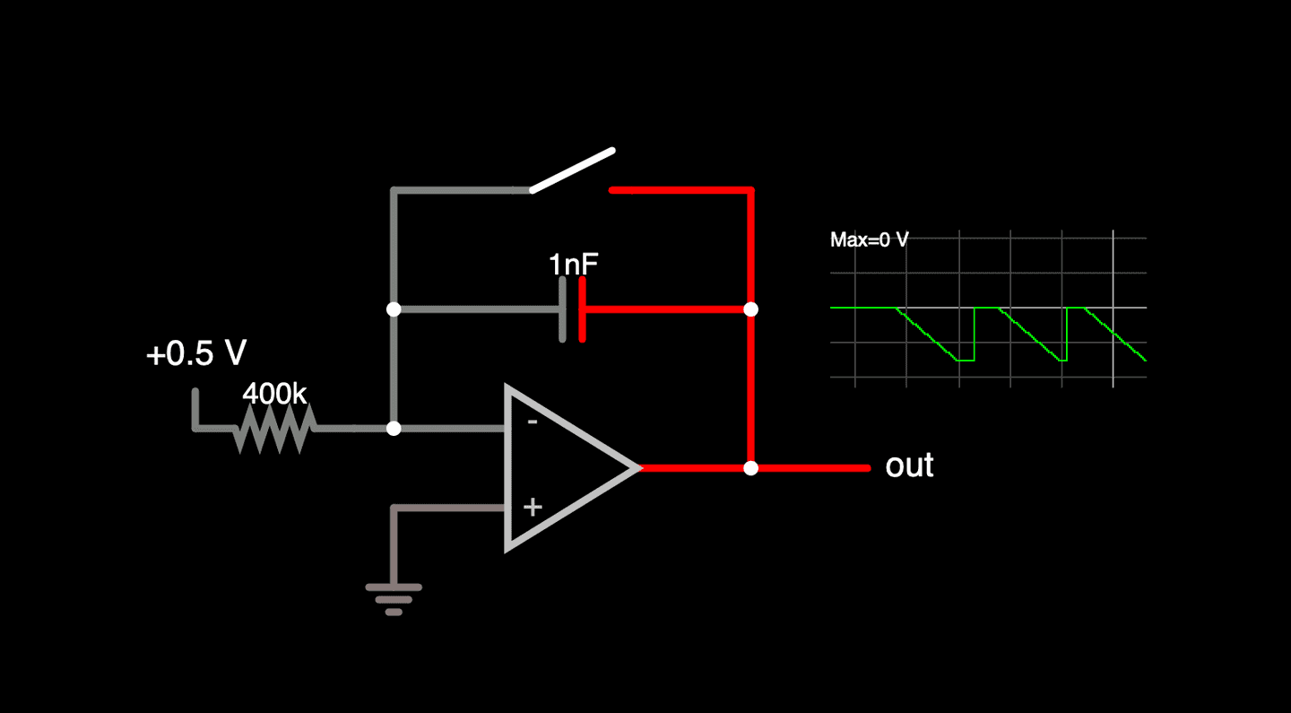
In the previous article we saw how adding a transistor as a switch in the ramp circuit allowed us to reset the ramp quickly to zero volts when we applied a small negative voltage (around -0.5 volts in our example) to the base of the transistor. Any voltage above that and the ramp goes from zero towards the negative supply voltage.
However, the clock we created in an even earlier article goes from 0 to 3.3 volts. We need to be able to turn some part of that clock into a short negative voltage pulse to reset the ramp and then remain zero volts or greater until it's time to reset the ramp again.
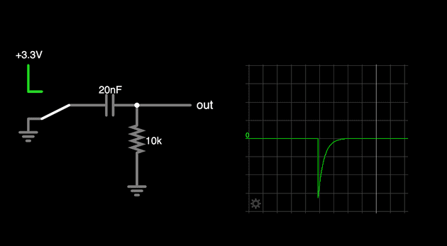
We can do this by putting a capacitor in series with our clock signal and looking at the voltage generated across a resistor connected to ground. In this circuit you can see this work when you change the switch from supplying 3.3 volts to ground (or zero volts) it produces a negative pulse measured between the output of the capacitor and the resistor. The positive pulse when moving the switch back to 3.3 volts doesn't matter as the transistor will stay shut off and the ramp will continue to fall as expected.
To understand why this happens, let's take a closer look at how capacitors work. A capacitor is made of two metal plates separated by an insulating material and it stores an electric charge on these plates. When the voltage applied to the input plate of the capacitor is at a positive value a charge builds up across the capacitor's plates with the input side being positively charged and the output side being negatively charged. The net charge on each plate must add to zero. When the voltage suddenly drops from 3.3 to zero volts, the charge on the input plate adjusts quickly to zero causing the charge on the output plate to change to match. This rapid change in stored charge causes the current to briefly create a negative voltage on the output side of the capacitor. The two plates reach equilibrium quickly which is why the pulse is so short.
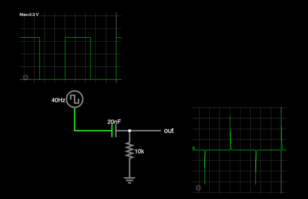
If we replace the switch with a square wave source we see the same negative and positive pulses corresponding to when the clock goes to zero or 3.3 volts (respectively). One thing to pay attention to with this circuit is how long the pulse lasts. A slider has been added to this example to vary the value of the capacitor and moving it you can see that smaler values make the pulse shorter while larger values make it longer. The key here is the pulse should be as short as it can while still letting the output of the ramp return to zero volts.
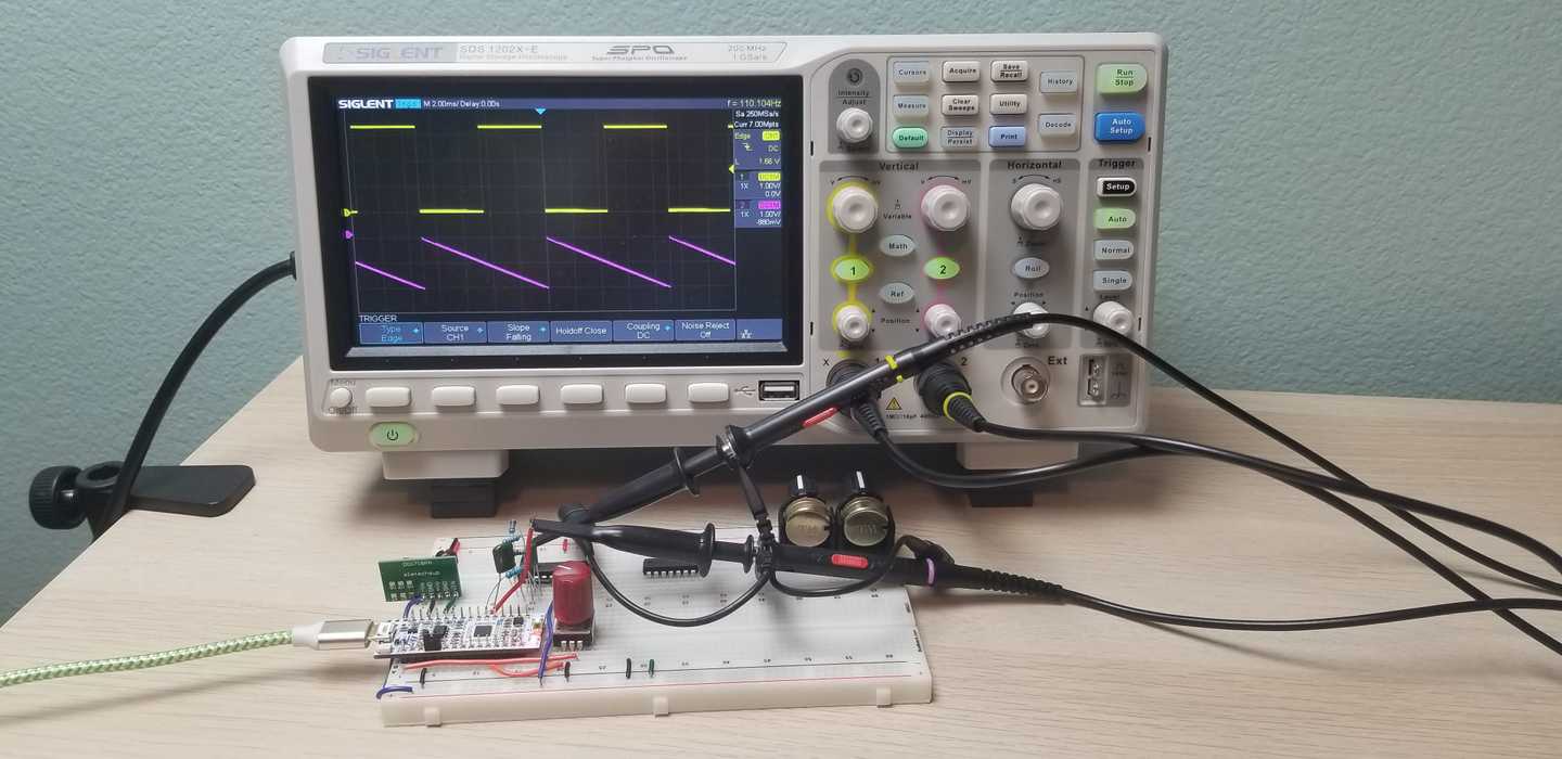
Finally, combining the clock with the rest of the circuit we get our repeating sawtooth wave. With the sawtooth reset mechanism in place, we’re getting closer to a fully functional DCO. In the next article, we’ll explore the link between clock frequency and ramp rate and see why we'll need to have a way to vary our ramp rate as the frequency changes.

