DCO Sawtooth: Ramp Reset
How to reset the sawtooth's ramp back to zero volts

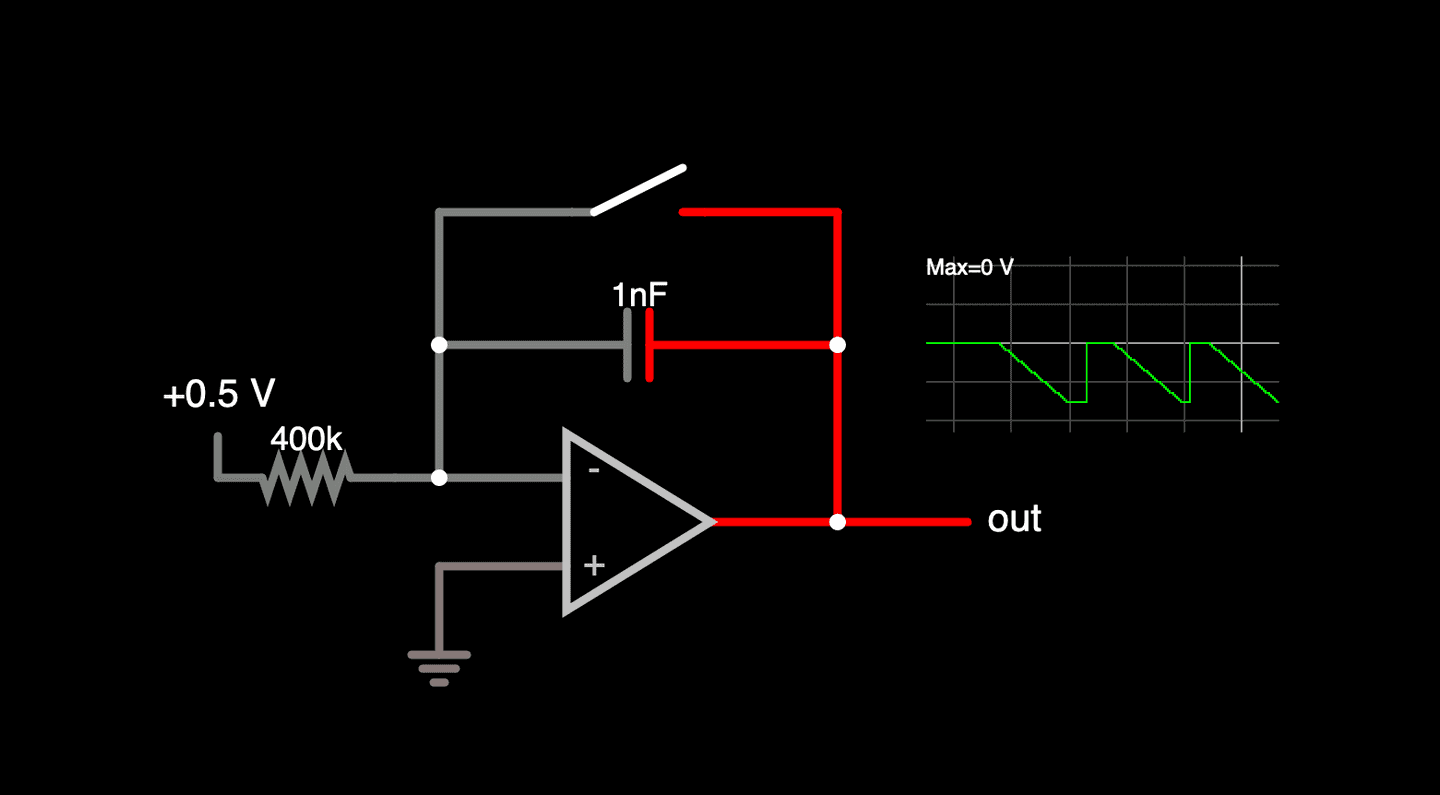
In the previous article we looked at how to create a linear ramping voltage using an op amp configured as an integrator and there was a link to a circuit simulation that demonstrated how this worked but also included a manual switch to reset the voltage.
First off, we're going to modify this circuit a bit because that original one used a negative voltage to control the slope of the ramp. It will be better for us if we make that control work from a positive voltage and the only difference is that the output will be a ramp going from zero volts to the negative supply voltage of the op amp. It's important to do that now because it will affect the components we choose for the ramp reset here in a bit.
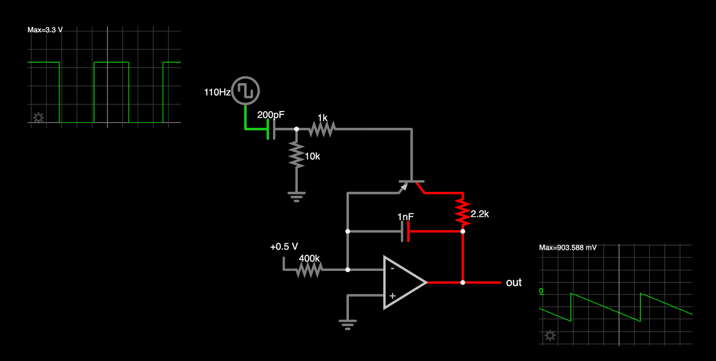
What we need to do automatically create the sawtooth is be able to use the square wave output of our microcontroller to effectively open and close the switch shorting out the capacitor in the op amp integrator. A simple way to do this is to use the switching characteristics of a transistor. So the switch can be replaced with this equivalent circuit:
You can see that you need to apply a negative voltage below about -0.5V to the base of the transistor to turn it on and allow the voltage to flow through it in a direction that will effectively short the integrator's capacitor. You can use the slider on the right of the page to see how the input voltage changes how the current flows through the transistor.
Combining this reset circuit with our integrator and adding a 2.2k resistor to limit the current through the transistor when it is turned on gives us the following circuit:
You can play with the circuit to see how all this works (again, use the voltage slider on the right). Now that we've replaced the manual switch with a transistor we can figure out how to turn the square wave from our microcontroller into an appropriately short negative pulse to properly operate this circuit and I'll get into that in the next article in this series.


