DCO Sawtooth: Keeping the Amplitude Constant as Frequency Changes
How to keep the amplitude of a sawtooth wave constant by controlling the input voltage of the ramp circuit.

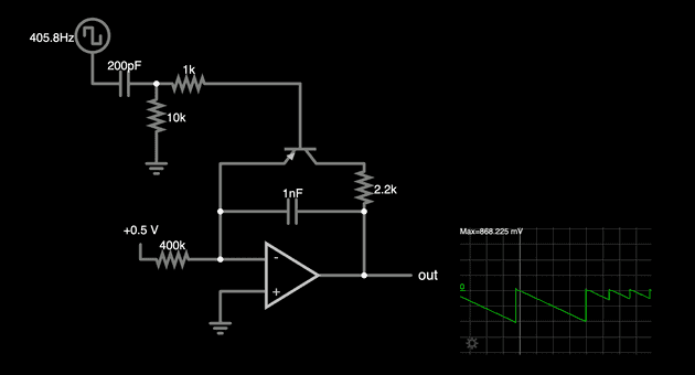
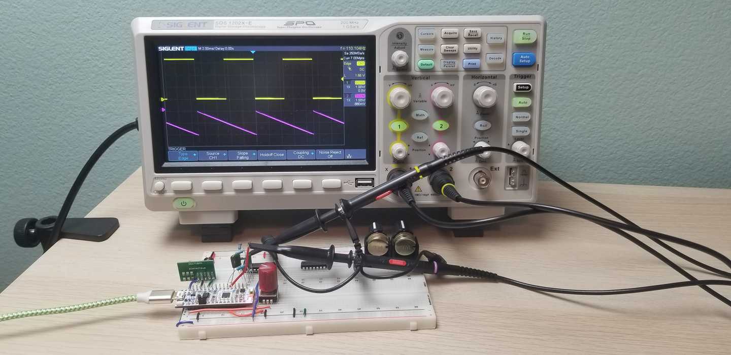
In the previous article we saw how to create a repeating sawtooth wave by combining our clock signal with the ramp generator. However, there's still one problem with that circuit: when we increase the frequency of the clock signal the amplitude of the sawtooth will decrease. The reason for this is that the ramp rate of our circuit is constant and as the frequency of the clock increases there isn't as much time for the fixed ramp to reach the same voltage each cycle. This can be seen in this example where you can vary the slider for the clock frequency and see the affect on the sawtooth amplitude.
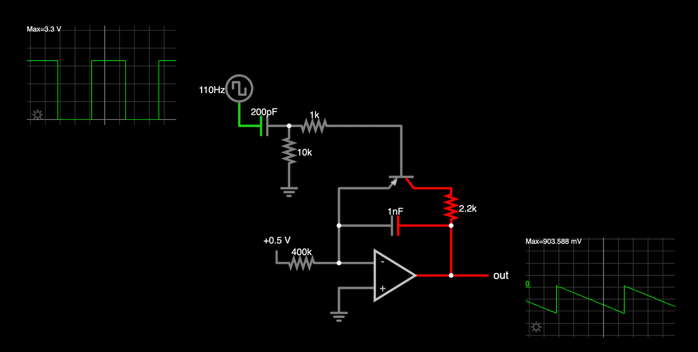
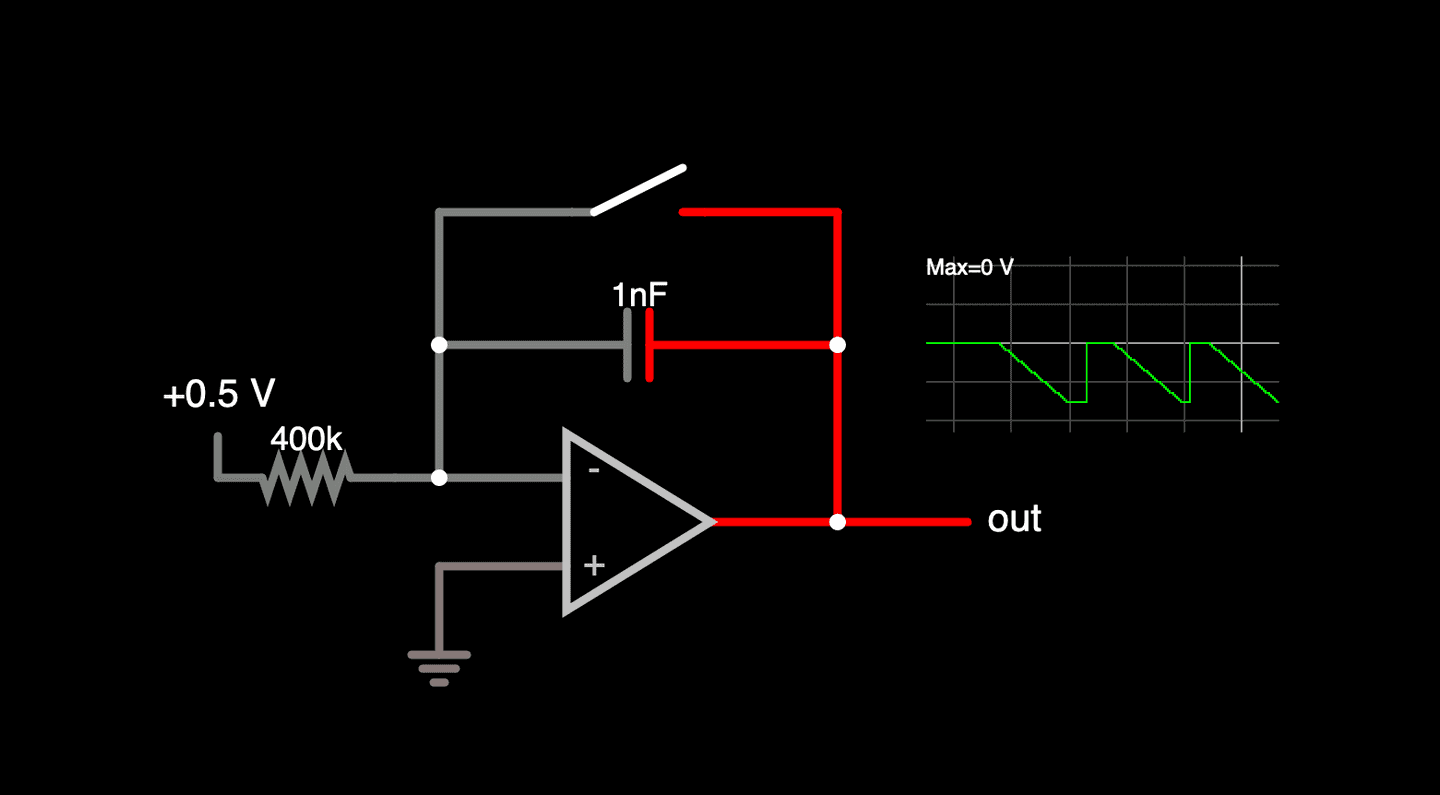
What we need to do is vary the ramp rate of our op amp integrator. Looking at the schematic above we can see there are three things that affect the ramp rate of the integrator: the input voltage, the resistor value, and the capacitor value. It turns out the math that represents the relationship between these three values is rather simple:
Note that the equation has a negative sign because the ramp goes negative when the input voltage is positive.
In the equation, is the input voltage (+0.5V in the example), is the value of the resistor (400KΩ), and is the value of the capacitor (1nF). This means that varying any one of those values will change the ramp rate. While there are circuits and mechanical ways to change the resistance or capacitance in a circuit it will be easiest for us to use one of the microcontroller's two DACs (digital-to-analog converter) to change the input voltage, thus varying the ramp rate.
Looking at the equation we see that increasing the input voltage will proportionally increase the ramp rate. Specifically, if we were to double the input voltage we'd also double the ramp rate. Thinking about our controlling clock, we can see that if we double the frequency we'll want to double the ramp rate to keep the amplitude constant.
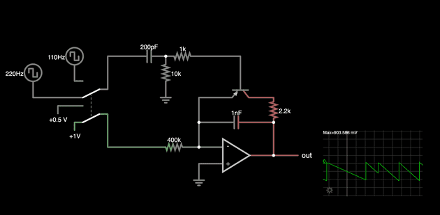
This example demonstrates that this will work by using a switch to both double the clock frequency into the circuit and the input voltage to the integrator. In the example we see that the amplitude of the sawtooth now remains constant (a cycle or so after the switch is changed).
Since we already went into a little bit of math let's check out how close the simulation of this circuit is to what it theoretically should be. We know that the ramp will go from zero to it's negative minimum over almost the entire period of the clock signal. The period of the clock (T) can be found from the clock frequency (f) with this equation:
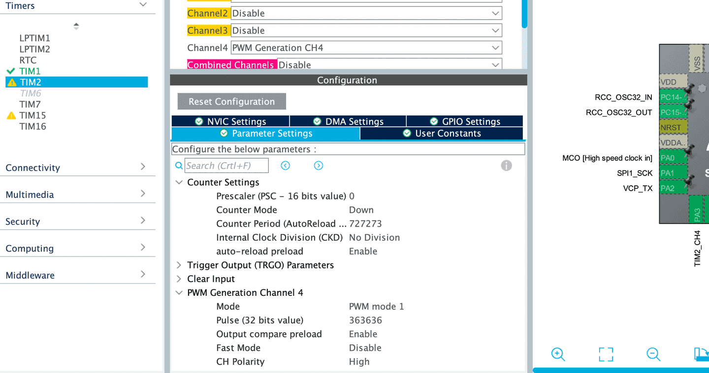
Our clock in this example is 110Hz so substituting:
Going back to the ramp equation, using the values from our circuit:
And plugging these in we get:
Finally we can multiply the ramp rate by the period of the clock signal to find the amplitude of the sawtooth wave:
Taking a look at the simulations we see that the sawtooth is reaching about -10.8V before it resets which is pretty close to the theoretical value. This is expected as there are things in the simulation that aren't accounted for like how long the reset lasts. Besides, the components and voltages in an actual circuit will have variances that will probably exceed the difference between these theoretical and simulated values.
In the next article we'll look at how we generate from the microcontroller's DAC and some practical considerations for being able to use across the whole frequency range we'll want our DCO to cover.

